并聯運行發電機組的調壓及無功功率分配
發電廠母線電壓的調節和機組間無功功率的分配是密切相關的,這種調節和分配通常是由發電機的自動勵磁調節器來實現的�����。
在穩定運行情況下���,發電機端電壓U與該電機無功電流I Q之間的關系U=f(IQ)稱為發電機的調節特性���。它可以近似用一條直線代表�,如圖一所示�����。
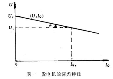
圖一 發電機的調差特性
為了定量地表示調節特性��,采用了調差系數的概念�����,發電機空載電壓與滿載電壓之差對額定電壓之比稱作調差系數K�。
上式中符號“一”表示無功負載增加電壓下降時的調差系數為正�����,反之為負��。
如果K≠0�,稱作有差特性��;K=0稱作無差特性��。
當發電廠中幾臺發電機并聯運行時,母線電壓水平和無功功率在機組間的分配決定于各臺機組的自動勵磁裝置的特性����,即決定于各臺發電機的電壓調節特性。
一����、幾臺具有無差特性調壓器的機組不能并聯運行
假定有兩臺具有無差特性調壓器的發電機并聯在母線上,如圖二所示�����。U 1表示第一臺發電機調壓器的電壓整定位����,UII表示第二臺發電機的電壓整定位,設U II>U IO
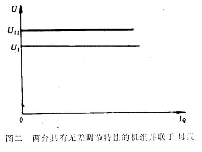
圖二 兩臺具有無差調節特性的機組并聯于母線
現在假定母線上的電壓低于U1和UII�����,這時兩臺機的調壓器要增加自己發電機的勵磁電流,母線電壓便開始上升���。當電壓升到U 1時�����,第一臺發電機的調壓器就不再增加勵磁了��,但第二臺機的調壓器還繼續增加勵磁電流�����,因為母線電壓決定于這兩臺機的勵磁�,它將由于第二臺機調壓器的作用而繼續上升��。當母線電壓數值在U1與U 11之間時�����,第一臺機的調壓器就開始減少勵磁電流�����,而第二臺機的調壓器仍繼續增加勵磁電流��。最后,第一臺調壓器使第一臺機的勵磁電流達到最低值�����,而第二臺機則把母線電壓提高到UII��,這時�����,第二臺機將負擔發電廠全部無功負荷����,而第一臺機不但卸去了它原來的無功負荷,而且可能吸取無功功率��。顯然��,這種方式是完全不能采用的����。
現在假定整定一下調壓器的整定元件����,使圖二中的兩條電壓調節特性曲線重合�����,這時母線電壓等于兩個調壓器的共同整定值�����,但無功功率將在這兩臺發電機之間任意分配���。無功功率在機組間的分配不確定是不允許的����,因為在這種情況下不可能穩定并聯運行。
二����、一臺具有無差特性的機組與一臺或幾臺具有有差特性的機組并聯運行���。
假設第一臺發電機具有無差特性��,其調節特性如圖三曲線I����,第二臺發電機具有有差特性,其調節特性如圖三曲線II����。
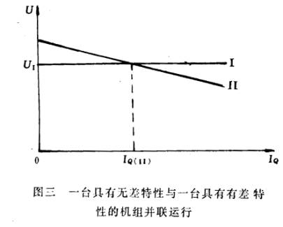
圖三 一臺具有無差特性與一臺具有有差特性的機組并聯運行
這時母線電壓為U 1并保持不變����,第二臺發電機無功負荷電流為IQ(11)是確定的����,由于用戶所需要的全部無功功率是由這兩臺機共同負擔的����,所以第一臺機負擔的無功電流也是確定的��。
三���、幾臺具有有差調節特性的發電機并聯運行在公共母線上���。
假設有兩臺具有有差特性的發電機并聯在母線上運行,其有差調節特性分別為圖四中心曲線I和曲線II。這時�����,兩臺發電機分端電是相同的����,等于母線電壓����,例如U′����,每臺電機負擔的無功功率是很確定的�����,例如分別I′Q(I)和1′Q(II)?��,F在假設用戶需要的無功電流增加了����,于是母線電壓下降,接著調壓器動作���,增加發電機的勵磁電流,最后母線電壓達到新的穩態值U″����,每臺機負擔的無功電流增加到新的定值I″Q(I)和I″Q(II)。
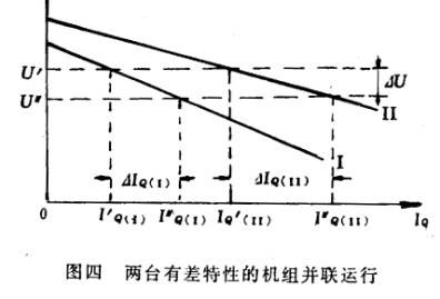
如果在運行中需要改變一臺發電機的無功負荷����,只須運行人員調整一下調壓器的整定元件,使調節特性曲線上移或下移即可�����。如果要求不改變無功負荷的分配比例���,只改變發電廠母線電壓���;那就需要以同一程度移上或移下所有并聯運行的發電機的調節特性曲線����。
下面討論發電機無功電流的改變量和電壓偏差以及調差系數的關系����。
公式(6)可以改寫成如下的形式

由公式(7)可以清楚地看出�,發電機無功電流的改變量與電壓偏差成正比�����,與調差系數成反比。因此�,調差系數較小的發電機將要多分擔無功電流的增量����。通常要求無功電流的
增量在機組間的分配與發電機額定容量成正比,即希望各臺機組無功電流增量的標么值ΔIQ*接近相等��。而此值等于一ΔU*/K,由于各臺機組并聯運行于母線�,故ΔU*是相同,因此這就要求各臺發電機的調壓器具有接近相等的調差系數����。
由上述可見����,幾臺具有有差特性的發電機可以并聯運行在公共母線上,機組間無功負荷的分配比例是確定的����,并且是可以調節的。
四�����、兩臺具有無差特性的發電機組經過一定的阻抗并聯運行
但是,兩臺具有無差特性的發電機組如經過一定的阻抗再行并聯����,例如發電機經升壓變壓器在高壓母線上并列����,則是允許的��。因為這時雖然發電機的調節特性是無羞的��,但由于變壓器本身有一個隨負載電流變化的阻抗壓降�,所以在高壓母線上的綜合結果使其具有了有差調節特性����,因此,允許并聯運行�。
Parallel operation of generator voltage and reactive power allocation
Power plant bus voltage regulation and unit of reactive power distribution is closely related to, the regulation and the distribution is usually composed of generator automatic voltage regulator to achieve.
In a stable operation condition, generator terminal voltage and reactive current of the motor is U I Q the relationship between U = f ( IQ ) called generator regulation characteristic. It can be approximated by a linear representation, as shown in fig..
Map generator voltage adjustment characteristic
In order to quantitatively express the regulation characteristic, adopts the difference coefficient concept, generator no-load voltage and full load voltage difference of rated voltage ratio called the difference coefficient K.
On the symbol" a" said reactive load increased voltage is decreased when the difference coefficient is positive, but negative.
If K ≠ 0, called differential characteristic; K = 0is called no differential characteristics.
When a power plant in a few generator running in parallel, the bus voltage and reactive power in the unit of allocation decisions in various units of automatic excitation device characteristics, which is determined by the generator voltage regulation characteristic.
A few stations, has no differential characteristics of pressure regulator unit is not operating in parallel
It is assumed that there are two stations with no differential characteristics of voltage regulator of the generator in parallel bus, as shown in figure two. U 1the first generator voltage regulator voltage adjusting positioning, said UII second generator voltage adjusting positioning, let U II > U IO
Figure two two has no control characteristic set parallel to the busbar
Now suppose that on the busbar voltage is lower than U1and UII, then the two machine regulator to increase the excitation current of the generator, the bus voltage begins to rise. When the voltage up to U 1, the first generator regulator will no longer increase excitation, but second machines in the regulator also continues to increase in the excitation current, because the bus voltage depends on the two machine excitation, it will be due to second machine regulator role and continue to rise. When the bus voltage values in U1and U between 11, the first machine regulator began to reduce the excitation current, and second machines in the pressure regulator is still increasing excitation current. Finally, the first pressure regulator so that the first machine excitation current reaches a minimum value, and the second is the bus voltage up to UII, then, second machines will burden all reactive load of power plant, and the first machine not only to its original reactive load, but also can absorb reactive power power. Obviously, this way is not used.
Now suppose that setting a lower pressure setting device, so that the second picture of the two voltage regulation characteristic curve coincidence, when the bus voltage is equal to the two voltage regulator of the common setting value, but the reactive power in the two generators which between arbitrary distribution. Reactive power in power distribution between the uncertainty is not allowed, because in this case cannot be stabilized in parallel operation.
In two, one has no difference characteristics of units and one or several has the difference characteristic of units operating in parallel.
Assuming the first generator has no difference characteristics, its regulation characteristics such as figure three curve I, second generators with a differential characteristics, its regulation characteristics such as figure three curve II.
Figure three one has no difference characteristics and a differential characteristics of the units operating in parallel
When the bus voltage to U 1and remained unchanged, second generators reactive load current of IQ (11) is determined, because the user needs all the reactive power is provided by the two machine joint burden, so the first machine burden of reactive current is determined by the.
In three, a few have difference regulating characteristics of generators operating in parallel in a public bus.
Hypothesis two has a characteristic of generator parallel operation in the bus, its differential regulation characteristics are figure four center curve and curve of I II. Then, two generators of end electric is the same, equal to the bus voltage, such as U′, each motor load reactive power is determined, for example, I′ Q ( I ) and 1′ Q ( II ). Now suppose that the user needs and reactive current is increased, so the bus voltage drop, then the regulator movement, increasing the excitation current of the generator, the last bus voltage to a new steady state value U ", each machine burden of reactive current increases to the new value of I" Q ( I ) and Q ( I ″II ).
If the operation of the need for change a generator reactive load, as long as the operator to adjust a downward pressure setting device, so that the regulation characteristic curve to move up or down. If the request is not change of reactive load distribution ratio, only change the power plant bus voltage; it needs to the same extent moved upwards or downwards all parallel operation of generator regulation characteristic curve.
The following discussion on generator reactive current changes and voltage deviation and difference coefficient relationship.
Equation (6) can be rewritten into the following form
By the formula (7) can be seen clearly, generator reactive power and the change of the current and voltage proportional to deviation, and difference coefficient is inversely proportional. Therefore, difference coefficient smaller generators will be more sharing of reactive current increment. Usually require reactive current
Increment in the unit of allocation and generator rated capacity is proportional to, that is hope that all units of reactive current increment of preunit valueΔ IQ* nearly equal. This value is equal to aΔ U* / K, due to various units operating in parallel on the bus, so theΔ U* is the same, so it requires the generator voltage regulator with approximately equal difference coefficient.
Visible from above, a few have difference characteristics of the generator can be parallel operation in public bus, unit of reactive load distribution ratio is determined, and is adjustable.
Four, two have no difference characteristics of generator after a certain amount of impedance in parallel operation
However, two has no difference characteristics of generating units such as the impedance and parallel, for example generators by the step-up transformer in high voltage bus in parallel, is permitted. Because although generator regulation characteristic is no shame, but because the transformer itself has a load current changes in the impedance drop, so in the high voltage bus on the integrated results which has a control characteristic, thus, allowing parallel running.
 English
 Espaol
 Franais
 阿拉伯
阿拉伯 中文(簡)
中文(簡) Deutsch
 Italiano
 Português
 日本
日本 韓國
韓國 български
 hrvatski
 esky
esky Dansk
Dansk Nederlands
 suomi
suomi Ελληνικ
 印度
印度 norsk
norsk Polski
 Roman
Roman русский
 Svenska